Series Magnetic Circuit
Definition: The Series Magnetic Circuit is defined as the magnetic circuit having a number of parts of different dimensions and materials carrying the same magnetic field. Consider a circular coil or solenoid having different dimensions as shown in the figure below
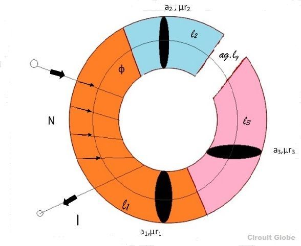
Current I is passed through the solenoid having N number of turns wound on the one section of the circular coil. Φ is the flux, sets up in the core of the coil.
a1, a2, a3 are the cross-sectional area of the solenoid.
l1, l2, l3 are the length of the three different coils having different dimension joined together in series.
µr1, µr2, µr3 are the relative permeability of the material of the circular coil.
ag and are the area and the length of the air gap.
The total reluctance (S) of the magnetic circuit is
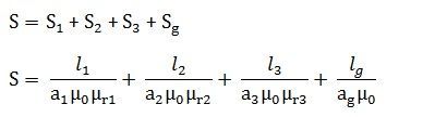
Total MMF = φ x S ……..…. (1)
Series Magnetic Circuit
Definition: The Series Magnetic Circuit is defined as the magnetic circuit having a number of parts of different dimensions and materials carrying the same magnetic field. Consider a circular coil or solenoid having different dimensions as shown in the figure below
Current I is passed through the solenoid having N number of turns wound on the one section of the circular coil. Φ is the flux, sets up in the core of the coil.
a1, a2, a3 are the cross-sectional area of the solenoid.
l1, l2, l3 are the length of the three different coils having different dimension joined together in series.
µr1, µr2, µr3 are the relative permeability of the material of the circular coil.
ag and are the area and the length of the air gap.
The total reluctance (S) of the magnetic circuit is
Total MMF = φ x S ……..…. (1)
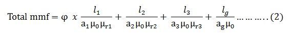
Putting the value of S in equation (1) we get
 (As B = φ/a) putting the valve of B in the equation (2) we obtain the following equation for the total MMF
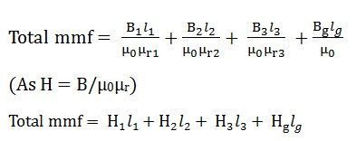
Procedure for the Calculation of the total MMF for the Series Magnetic Circuit
- The magnetic circuit is divided into a different section or parts.
- Now determine the value of the flux density (B) of the different sections. As we know B = φ/a where φ is the flux in Weber, and a is the area of cross-section in m2
- Determine the value of the magnetising force (H) as we know that H = B/µ0µr where B is the flux density in Weber/ m2 and µ0 is absolute permeability and its value is 4πx10-7, and µr is the relative permeability of the material, and its value will be given. If the value of µr is not given, then you have to compute the value from the value of H from the B-H curve
- The value of magnetising force (H) as H1, H2, H3, Hg will be individually multiplied by the length of the different sections that is, l1, l2, l3 and lg respectively.
- Finally, add all the values of Hx l and therefore, the total MMF will be
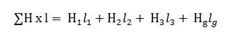
The value of H for the air gap part will always µg = B/µ0.
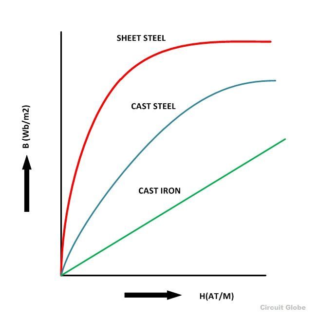
B-H Curve
The graph plotted between the flux density (B) and the magnetising force (H) of any material is called B-H Curve or the magnetisation curve.
The shape of the B-H curve is mostly non-linear this means that the relative permeability (µr) of the material varies and is not constant. The value of relative permeability mainly depends on the value of flux density. But for the non-magnetic materials like plastic, rubber, etc. and for the magnetic circuit having an air gap, its value is constant, denoted by (µ0). Its value is 4πx10-7H/m and commonly known as absolute permeability or permeability of free space.
B-H curve for the various material like cast iron, cast steel and sheet steel is shown below.


No comments:
Post a Comment