Differential Protection Relay
Definition: The relay whose operation depends on the phase difference of two or more electrical quantities is known as the differential protection relay. It works on the principle of comparison between the phase angle and the magnitude of the same electrical quantities.
For example: Consider the comparison of the input and output current of the transmission line. If the magnitude of the input current of the transmission line is more than that of output current that means the additional current flows through it because of the fault. The difference in the current can operate the differential protection relay.
The following are the essential condition requires for the working of the differential protection relay.
- The network in which the relay use should have two or more similar electrical quantities.
- The quantities have the phase displacement of approximately 180º.
The differential protection relay is used for the protection of the generator, transformer, feeder, large motor, bus-bars etc. The following are the classification of the differential protection relay.
- Current Differential Relay
- Voltage Differential Relay
- Biased or Percentage Differential Relay
- Voltage Balance Differential Relay
Current Differential Relay
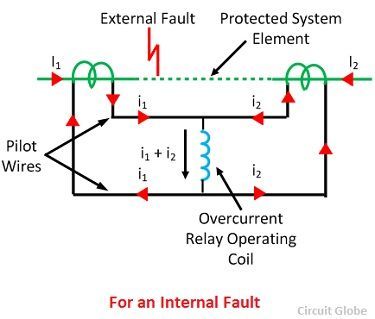
A relay which senses and operates the phase difference between the current entering into the electrical system and the current leaving the electrical system is called a current differential relay. An arrangement of overcurrent relay connected to operate as a differential relay is shown in the figure below.
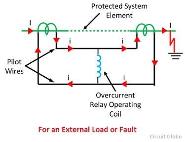 The arrangement of the overcurrent relay is shown in the figure below. The dotted line shows the section which is used to be protected. The current transformer is placed at both the ends of the protection zone. The secondary of the transformers is connected in series with the help of the pilot wire. Thereby, the current induces in the CTs flows in the same direction. The operating coil of the relay is connected on the secondary of the CTs.
In the normal operating condition, the magnitude of current in the secondary of the CTs remains same. The zero current flows through the operating coil. On the occurrence of the fault, the magnitude of the current on the secondary of CTs becomes unequal because of which the relay starts operating.
Biased or Percentage Differential Coil
This is the most used form of differential relay. Their arrangement is same as that of the current differential relay; the only difference is that this system consists an additional restraining coil connected in the pilot wires as shown in the figure below.
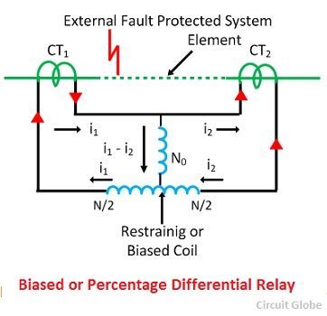 The operating coil connects in the centre of the restraining coil. The ratio of current in the current transformer becomes unbalance because of the fault current. This problem is resolved by the use of the restraining coil.
Induction Type Biased Differential Relay
This induction type relay consists a disc which freely rotates between the electromagnets. The each of the electromagnet consists the copper shading ring. The ring can move in or out of the electromagnet. The disc experiences a force because of the restraining and the operating element.
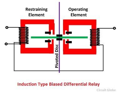 The resultant torque on the shaded ring becomes zero if the position of the ring is balanced for both the element. But if ring moves towards the iron core then the unequal torques acting on the ring because of the operating and restraining coil.
Voltage Balance Differential Relay
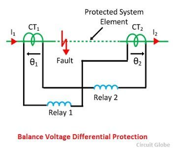
The current differential relay is not suitable for the protection of the feeders. For the protection of the feeders, the voltage balance differential relays are used. The voltage differential relay uses two similar current transformer places across the protective zone with the help of pilot wire.
The relays are connected in series with the secondary of the current transformer. The relays are connected in such a way that no current flows through it in the normal operating condition. The voltage balance differential relay uses the air core CTs in which the voltages induces regarding current.
No comments:
Post a Comment