Friday, 24 May 2019

Advantages of 3 Phase Over Single Phase System

Advantages of 3 Phase Over Single Phase System

The three-phase system has three live conductors which supply the 440V to the large consumers. While the single phase system has one live conductor which is used for domestic purposes. The following are the main advantages of 3 Phase system over Single Phase system.
  • Higher Rating
    The rating, i.e. the output of a three-phase machine is nearly 1.5 times the rating (output) of a single phase machine of the same size.
  • Constant Power
    In single phase circuits, the power delivered is pulsating. Even when the voltage and current are in phase, the power is zero twice in each cycle. Whereas, in the polyphase system, the power delivered is almost constant when the loads are in balanced condition.
  • Power Transmission Economics
    The three phase system requires only 75% of the weight of conducting material of that required by single phase system to transmit the same amount of power over a fixed distance at a given voltage.
  • Superiority of 3 Phase Induction Motors
    The three Phase induction motors have a widespread field of applications in the industries because of the following advantages are given below.
1. Three phase induction motors are self-starting whereas the single phase induction motor is not self-starting. This means the 1 –phase motor has no starting torque and hence it needs some auxiliary means to start at the initial stage.
2. The three Phase Induction motors have higher power factor and efficiency than that of a single phase induction motor.
  • Size and Weight of alternator
    The 3 Phase Alternator is small in size and light in weight as compared to a single phase alternator.
  • Requirement of Copper and Aluminium
    3 Phase system requires less copper and aluminium for the transmission system in comparison to a single phase transmission system.
  • Frequency of Vibration
    In 3 phase motor, the frequency of vibrations is less as compared to single phase motor because in single phase the power transferred is a function of current and varies constantly.
  • Dependency
    A single phase load can be efficiently fed by a 3 phase load or system, but 3 phase system cannot depend or feed by a single phase system.
  • Torque
    A uniform or constant torque is produced in a 3 phase system, whereas in a single phase system pulsating torque is produced.
Difference Between Single Phase and Three Phase Induction Motor

Difference Between Single Phase and Three Phase Induction Motor

The Single Phase and Three Phase Induction Motor is differentiated on the various factors in this article such as the Supply on which they operate, their starting torque, maintenance, features, the efficiency of the motor, their power factors and the example where the two motors are used.
Difference Between Single Phase and Three Phase Induction Motor are given below in tabulated form.
BASISSINGLE PHASE INDUCTION MOTORTHREE PHASE INDUCTION MOTOR
SupplySingle Phase induction motor uses single phase supply, for its operation.Three Phase induction motor uses three phase supply, for its operation.
Starting torqueThe starting torque is low.The starting torque is high.
MaintenanceThey are easy to repair and maintain.Difficult to repair and maintain.
FeaturesSimple in construction, reliable and economical as compared to three phase induction motors.Complex in construction and costly.
EfficiencyEfficiency is lessEfficiency is high
Power factorPower factor is lowPower factor is high
ExamplesThey are mostly used in domestic appliances such as mixer grinder, fans, compressors etcThree phase induction motors are mostly used in industries.
The Induction Motor is an asynchronous motor as they do not run at the synchronous speed. The Single Phase Induction motor work on the 1 phase supply power and is not self-starting.
The three phase induction motor works on the 3 phase power supply mains and is self-starting motor.

Difference Between Single Phase and Three Phase Induction Motor are as follows:-

  • As the name itself shows, the Single Phase induction motor uses single phase supply, for its operation and 3 Phase induction motor uses three phase supply.
  • The Starting Torque of Single Phase induction motor is low, whereas the starting torque of Three Phase Induction motor is high.
  • Single Phase motors are easy to repair and maintain, but the maintenance of three phase motors difficult.
  • Single Phase motors are simple in construction, reliable and economical as compared to three phase induction motors.
  • The efficiency of single phase motor is low, whereas the efficiency of three phase induction motors is high.
  • The power factor of Single Phase Induction motor is low as compared to that of three-phase induction motor.
  • Single Phase motors are mostly used in domestic appliances such as mixer grinder, fans, compressors, etc. Three phase induction motors are mostly used in the industries.

Working Principle of a Single Phase Induction Motor

Working Principle of a Single Phase Induction Motor

Single Phase Induction Motor consists of a single phase winding which is mounted on the stator of the motor and a cage winding placed on the rotor. A pulsating magnetic field is produced, when the stator winding of the single-phase induction motor shown below is energised by a single phase supply.
working-of-single-phase-induction-motor
The word Pulsating means that the field builds up in one direction falls to zero and then builds up in the opposite direction. Under these conditions, the rotor of an induction motor does not rotate. Hence, a single phase induction motor is not self-starting. It requires some special starting means.
If the 1 phase stator winding is excited and the rotor of the motor is rotated by an auxiliary means and the starting device is then removed, the motor continues to rotate in the direction in which it is started.
The performance of the single phase induction motor is analysed by the two theories. One is known as the Double Revolving Field Theory, and the other is Cross Field Theory. Both the theories are similar and explain the reason for the production of torque when the rotor is rotating.

Double Revolving Field Theory of Single Phase Induction Motor

The double revolving field theory of a single phase induction motor states that a pulsating magnetic field is resolved into two rotating magnetic fields. They are equal in magnitude but opposite in directions. The induction motor responds to each of the magnetic fields separately. The net torque in the motor is equal to the sum of the torque due to each of the two magnetic fields.
The equation for an alternating magnetic field is given as
working-principle-of-single-phase-indcution-motor-eq-1
Where βmax is the maximum value of the sinusoidally distributed air gap flux density produced by a properly distributed stator winding carrying an alternating current of the frequency ω, and α is the space displacement angle measured from the axis of the stator winding.
As we know,
working-principle-of-single-phase-indcution-motor-eq-2
So, the equation (1) can be written as
working-principle-of-single-phase-indcution-motor-eq-3j
The first term of the right-hand side of the equation (2) represents the revolving field moving in the positive α direction. It is known as a Forward Rotating field. Similarly, the second term shows the revolving field moving in the negative α direction and is known as the Backward Rotating field.
The direction in which the single phase motor is started initially is known as the positive direction. Both the revolving field rotates at the synchronous speed. ω= 2πf in the opposite direction. Thus, the pulsating magnetic field is resolved into two rotating magnetic fields. Both are equal in magnitude and opposite in direction but at the same frequency.
At the standstill condition, the induced voltages are equal and opposite as a result; the two torques are also equal and opposite. Thus, the net torque is zero and, therefore, a single phase induction motor has no starting torque.

Equivalent Circuit of a Single Phase Induction Motor

Equivalent Circuit of a Single Phase Induction Motor

The Equivalent circuit of a Single Phase Induction Motor can be obtained by two methods named as the Double Revolving Field Theory and Cross Field Theory. Firstly the equivalent circuit is developed on the basis of double revolving field theory when only its main winding is energized.
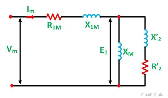
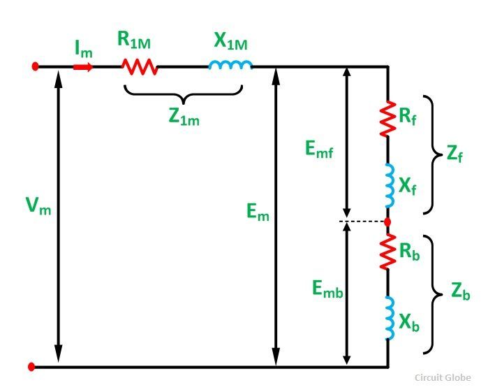
Considering the case when the rotor is stationary and only the main winding is excited. The motor behaves as a single phase transformer with its secondary short circuited. The equivalent circuit diagram of the single phase motor with only its main winding energized the is shown below.
EQUIVALENT-CIRCUIT-OF-A-SINGLE-PHASE-INDUCTION-MOTOR-FIG-1
Here,
  • R1m is the resistance of the main stator winding.
  • X1m is the leakage reactance of the main stator winding.
  • Xis the magnetizing reactance.
  • R’2 is the standstill rotor resistance referred to the main stator winding.
  • X’2 is the standstill rotor leakage reactance referred to the main stator winding.
  • Vis the applied voltage.
  • Im is the main winding current.
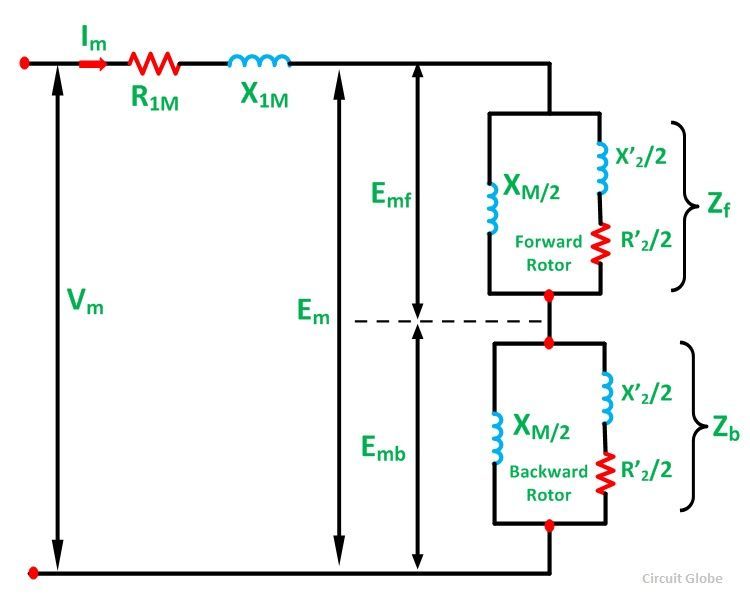
The core loss will be assumed to be lumped with the mechanical and stray losses as a part of the rotational losses of the rotor. The pulsating air gap flux in the motor at the standstill is resolved into two equal and opposite fluxes with the motor. The standstill impedance of each of the rotor referred to the main stator winding is given as
Equivalent-circuit-of-1-phase-indcution-motor-eq-1
The equivalent circuit of a single phase single winding induction motor with the standstill rotor is shown below. The forward and the backward flux induces a voltage Emf and Emb respectively in the main stator winding. Em is the resultant induced voltage in the main winding.
Equivalent-circuit-of-1-phase-indcution-motor-eq-2
At the standstill condition Emf = Emb
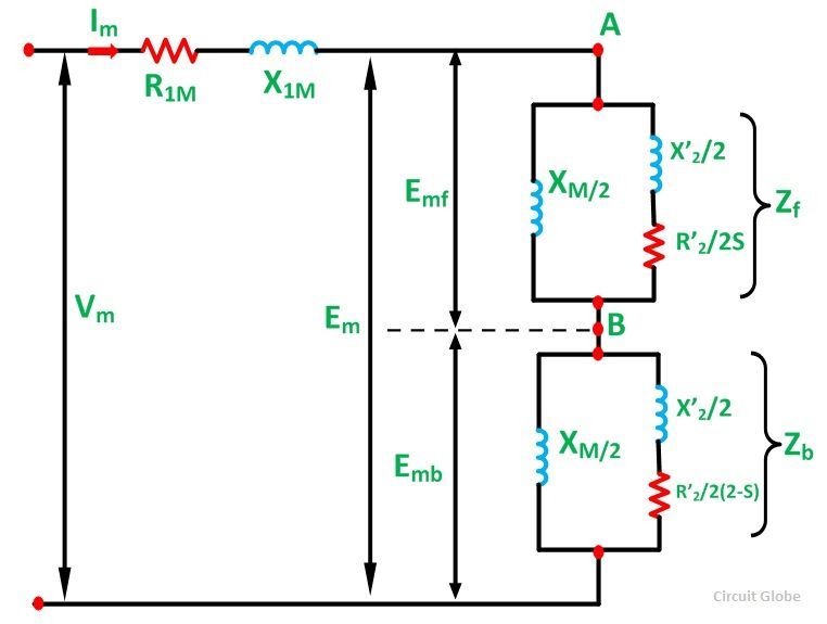
Now, with the help of an auxiliary winding the motor is started. As the motor attains its normal speed, the auxiliary winding is removed. The effective rotor resistance of an induction motor depends on the slip of the rotor.

EQUIVALENT-CIRCUIT-OF-A-SINGLE-PHASE-INDUCTION-MOTOR-FIG-2
In the above circuit diagram, the air gap portion is split into two parts. The first part shows the effect of forward rotating flux and the second parts shows the effect of the backward rotating flux. The effective rotor resistance with respect to the forward rotating flux is R’2/2S and with respect to the backward rotating flux is R’2/2 (2-s).
When both forward and backward slips are taken into account, the equivalent circuit shown below is formed. In this condition, the motor is running on the main winding alone.
EQUIVALENT-CIRCUIT-OF-A-SINGLE-PHASE-INDUCTION-MOTOR-FIG-3
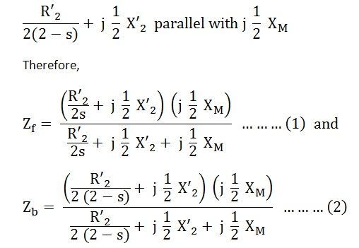
The rotor impedance representing the effect of the forward field referred to the stator winding m is given by an impedance shown below.
Equivalent-circuit-of-1-phase-indcution-motor-eq-3
The rotor impedance of a single phase induction motor representing the effect of the backward field referred to the stator winding m is given by an impedance shown below.
Equivalent-circuit-of-1-phase-indcution-motor-eq-4
The simplified equivalent circuit of a single phase induction motor with only its main winding energized is shown in the figure below.
Single phase induction motor figure 4
Here,
Equivalent-circuit-of-1-phase-indcution-motor-eq-5
The above equation (3) is the equation of the current in the stator winding

Starting Methods of a Single Phase Induction Motor

Starting Methods of a Single Phase Induction Motor

The Single Phase Motor is not self starting and hence needs an auxiliary means or equipment to start the single phase induction motor. Mechanical methods are impractical and, therefore the motor is started temporarily converting it into two phase motor.
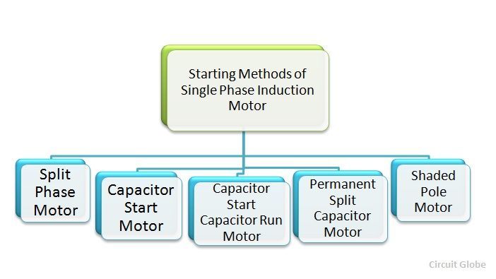
Single phase Induction motors are usually classified according to the auxiliary means used to start the motor. They are classified according to the starting methods.
STARTING METHOD OF SINGLE PHASE INDUCTION MOTOR
The various Starting methods of a Single Phase Induction motor are as follows:-
All these starting methods are explained individually in detail in the separate articles. These starting methods depend on the two alternating fields displaced in space and phase.
The rotating field is the resultant of the two individual fields. This rotating field reacts with the cage rotor to provide the starting torque. One field is produced by the field winding and the other by the auxiliary winding or the starting winding.

Capacitor Start Induction Motor

Capacitor Start Induction Motor

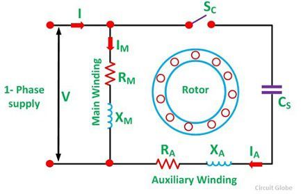
Capacitor Start Motors are a single phase Induction Motor that employs a capacitor in the auxiliary winding circuit to produce a greater phase difference between the current in the main and the auxiliary windings. The name capacitor starts itself shows that the motor uses a capacitor for the purpose of the starting. The figure below shows the connection diagram of a Capacitor Start Motor.
capacitor-run-motor-images
Contents:
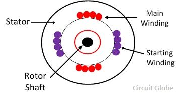
The capacitor start motor has a cage rotor and has two windings on the stator. They are known as the main winding and the auxiliary or the starting winding. The two windings are placed 90 degrees apart. A capacitor CS is connected in series with the starting winding. A centrifugal switch SC is also connected in the circuit.

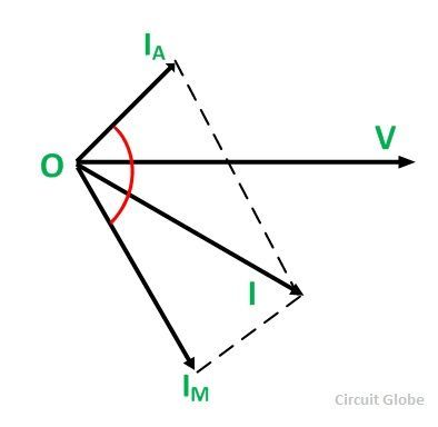
The Phasor Diagram of the Capacitor Start motor is shown below.
Capacitor-Start-Motor-fig-2
IM is the current in the main winding which is lagging the auxiliary current IAby 90 degrees as shown in the phasor diagram above. Thus, a single phase supply current is split into two phases. The two windings are displaced apart by 90 degrees electrical, and their MMF’s are equal in magnitude but 90 degrees apart in time phase.
The motor acts as a balanced two-phase motor. As the motor approaches its rated speed, the auxiliary winding and the starting capacitor is disconnected automatically by the centrifugal switch provided on the shaft of the motor.

Characteristics of the Capacitor Start Motor

The capacitor starts motor develops a much higher starting torque of about 3 to 4.5 times of the full load torque. To obtain a high starting torque, the two conditions are essential. They are as follows:-
  • The Starting capacitor value must be large.
  • The valve of the starting winding resistance must be low.
The electrolytic capacitors of the order of the 250 µF are used because of the high Var rating of the capacitor requirement.
The Torque Speed Characteristic of the motor is shown below.
Capacitor Start Indcution Motor figure 2
The characteristic shows that the starting torque is high. The cost of this motor is more as compared to the split phase motor because of the additional cost of the capacitor. The Capacitor start motor can be reversed by first bringing the motor to rest condition and then reversing the connections of one of the windings.

Applications of the Capacitor Start Motor

The various applications of the motor are as follows:
  • These motors are used for the loads of higher inertia where frequent starting is required.
  • Used in pumps and compressors
  • Used in the refrigerator and air conditioner compressors.
  • They are also used for conveyors and machine tools.

Split Phase Induction Motor

Split Phase Induction Motor

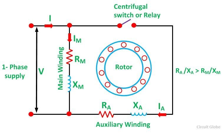
The Split Phase Motor is also known as a Resistance Start Motor. It has a single cage rotor, and its stator has two windings known as main winding and starting winding. Both the windings are displaced 90 degrees in space. The main winding has very low resistance and a high inductive reactance whereas the starting winding has high resistance and low inductive reactance.The Connection Diagram of the motor is shown below.

Split-Phase-Indcution-Motor-fig-1A resistor is connected in series with the auxiliary winding. The current in the two windings is not equal as a result the rotating field is not uniform. Hence, the starting torque is small, of the order of 1.5 to 2 times of the started running torque. At the starting of the motor both the windings are connected in parallel.
As soon as the motor reaches the speed of about 70 to 80 % of the synchronous speed the starting winding is disconnected automatically from the supply mains. If the motors are rated about 100 Watt or more, a centrifugal switch is used to disconnect the starting winding and for the smaller rating motors relay is used for the disconnecting of the winding.
A relay is connected in series with the main winding. At the starting, the heavy current flows in the circuit, and the contact of the relay gets closed. Thus, the starting winding is in the circuit, and as the motor attains the predetermined speed, the current in the relay starts decreasing. Therefore, the relay opens and disconnects the auxiliary winding from the supply, making the motor runs on the main winding only.
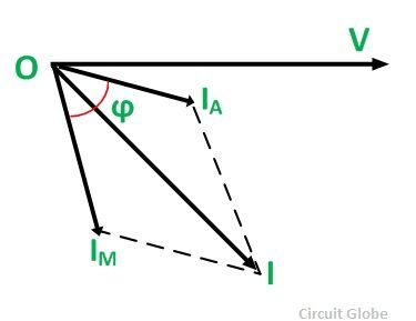
The phasor diagram of the Split Phase Induction Motor is shown below.
Split-Phase-Indcution-Motor-fig-2The current in the main winding (IM) lag behind the supply voltage V almost by the 90-degree angle. The current in the auxiliary winding IA is approximately in phase with the line voltage. Thus, there exists the time difference between the currents of the two windings. The time phase difference ϕ is not 90 degrees, but of the order of 30 degrees. This phase difference is enough to produce a rotating magnetic field.
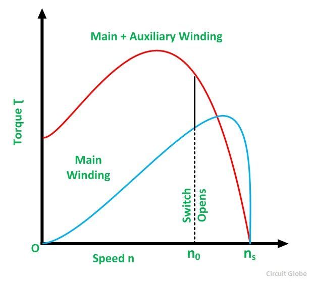
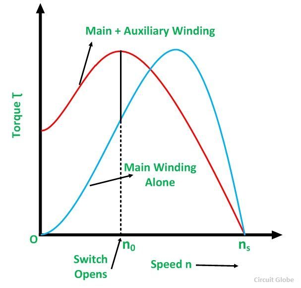
The Torque Speed Characteristic of the Split Phase motor is shown below.
Split Phase Induction Motor figure
Here, n0 is the point at which the centrifugal switch operates. The starting torque of the resistance start motor is about 1.5 times of the full load torque. The maximum torque is about 2.5 times of the full load torque at about 75% of the synchronous speed. The starting current of the motor is high about 7 to 8 times of the full load value.
The direction of the Resistance Start motor can be reversed by reversing the line connection of either the main winding or the starting winding. The reversal of the motor is possible at the standstill condition only.

Applications of Split Phase Induction Motor

This type of motors are cheap and are suitable for easily starting loads where the frequency of starting is limited. This type of motor is not used for drives which require more than 1 KW because of the low starting torque. 
The various applications are as follows:-
  • Used in the washing machine, and air conditioning fans.
  • The motors are used in mixer grinder, floor polishers.
  • Blowers, Centrifugal pumps
  • Drilling and lathe machine.

Difference between Induction Motor and Synchronous Motor

Difference between Induction Motor and Synchronous Motor

Difference Between Induction and Synchronous Motor is explained with the help of various factors, like the type of excitation used for the machine. The Speed of the motor, starting and operation, the efficiency of both the motors, its cost, usage, and applications. frequency.
BASIS OF DIFFERENCESYNCHRONOUS MOTORINDUCTION MOTOR
Type of ExcitationA synchronous motor is a doubly excited machine.An induction motor is a single excited machine.
Supply SystemIts armature winding is energized from an AC source and its field winding from a DC source.Its stator winding is energized from an AC source.
SpeedIt always runs at synchronous speed. The speed is independent of load.If the load increased the speed of the induction motor decreases. It is always less than the synchronous speed.
StartingIt is not self starting. It has to be run up to synchronous speed by any means before it can be synchronized to AC supply.Induction motor has self starting torque.
OperationA synchronous motor can be operated with lagging and leading power by changing its excitation.An induction motor operates only at a lagging power factor. At high loads the power factor becomes very poor.
UsageIt can be used for power factor correction in addition to supplying torque to drive mechanical loads.An induction motor is used for driving mechanical loads only.
EfficiencyIt is more efficient than an induction motor of the same output and voltage rating.Its efficiency is lesser than that of the synchronous motor of the same output and the voltage rating.
CostA synchronous motor is costlier than an induction motor of the same output and voltage ratingAn induction motor is cheaper than the synchronous motor of the same output and voltage rating.
An Induction Motor is also known as Asynchronous Motor. It is so called because it never runs at synchronous speed. i.e., Ns = 120f/P. The induction motor is most widely used motor in all domestic and commercial motor. The Synchronous motor always follows a synchronous speed. The speed of the rotor is maintained or synchronized with the supply current

Difference between Three Phase Induction Motor and Synchronous Motor

  • A three phase Synchronous motor is a doubly excited machine, whereas an induction motor is a single excited machine.
  • The armature winding of the Synchronous motor is energized from an AC source and its field winding from a DC source. The stator winding of Induction Motor is energized from an AC source.
  • Synchronous Motor always runs at synchronous speed, and the speed of the motor is independent of load, but an induction motor always runs less than the synchronous speed. If the load increased the speed of the induction motor decreases.
  • The induction motor has self-starting torque whereas the synchronous motor is not self starting. It has to be run up to synchronous speed by any means before it can be synchronized to AC supply.
  • A synchronous motor can be operated with lagging and leading power by changing its excitation. An induction motor operates only at a lagging power factor. At high loads, the power factor of the induction motor becomes very poor.
  • The Synchronous Motor can be used for power factor correction in addition to the supplying torque to drive mechanical loads whereas an induction motor is used for driving mechanical loads only.
  • The synchronous motor is more efficient than an induction motor of the same output and voltage rating.
  • A synchronous motor is costlier than an induction motor of the same output and voltage rating.

Synchronous Condensor

Synchronous Condensor

Synchronous Condensor is also known as Synchronous Compensator or Synchronous Phase Modifier. A synchronous condenser or a synchronous compensator is a synchronous motor running without a mechanical load. It can generate or absorb reactive volt-ampere (VAr) by varying the excitation of its field winding. It can be made to take a leading current with over-excitation of its field winding.
n such a case it delivers inductive or absorbs capacitive Volt-ampere reactive. If it is under the excited condition, it draws the lagging current and, therefore, supplies capacitive or absorbs inductive volt-ampere reactive. Thus, a current drawn by a synchronous capacitor or condenser can be varied from lagging to leading smoothly by varying its excitation.
When the motor power factor is unity, the DC excitation is said to be normal. Over-excitation causes the motor to operate at a leading power factor. Under excitation causes it to operate at a lagging power factor. When the motor is operated at no load with over-excitation, it takes a current that leads the voltage by nearly 90 degrees.
Thus, it behaves like a capacitor and under such operating conditions, the synchronous motor is called a synchronous capacitor.
Since a synchronous condenser behaves like a variable inductor or a variable capacitor, it is used in power transmission systems to regulate line voltage.

Power Factor Correction

Power Factor Correction

Definition: The power factor correction means bringing the power factor of anAC circuit nearer to one by using the equipment which absorbs or supply the reactive power to the circuit. Usually, the power factor correction can be done by using the capacitor and the synchronous motor in the circuit.The power factor correction will not change the amount of true power, but it will reduce the apparent power and the total current drawn from the load.
The phase shift between the voltage and the current of the circuit is known as the power factor. It is represented by the cosine of the angle φ. The power factor represents the fraction of total energy use for doing useful work, and the remaining energy is stored in the form of magnetic energy in the inductor and capacitor of the circuit. The value of power factor lies between -1 to +1.
The most economical value of power factor lies between 0.9 to 0.95. If the value of power factor lies below 0.8 (approx), then it draws more current from the load. The large current increases the losses and requires a large conductor, thus increases the cost of the system.The loss can be reduced by correcting the power factor of the system.

Power Factor Correction Methods

The power factor correction methods are mainly classified into two types, i.e., by using the capacitor or through the synchronous condenser.

Power Factor Correction by using Capacitor Bank

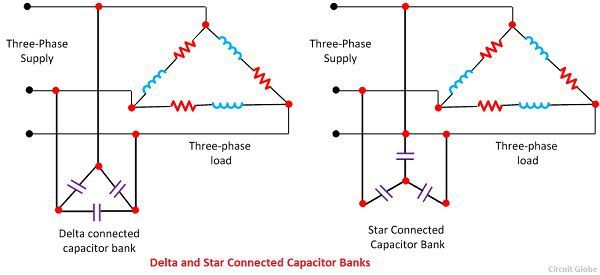
In three phase system, the power factor is improved by connecting the capacitors in star or delta. The star and delta connected banks are shown in the figure below.
power-factor-correction-imagesLet, VL = Line voltage
Vp = phase voltage
CΔ = capacitor per phase when the capacitors are connected in delta
Cy = capacitance per phase when the capacitor are connected in stars
Qc = Var rating of each phase
Delta Connection
power-factor-correction-equation-1The capacitance per phase is given by the equation
power-factor-correction-equation-2Star Connection
power-factor-correction-equation-3The capacitance per phase is expressed by the equation
power-factor-correction-equation-4From equation (1) and (2) we get
power-factor-correction-equation-5The equation (3) shows that the capacitance requires in star connection of three phase transformer is equal to three times the capacitance requires per phase when the capacitors are connected in delta. Also, the working voltage of the star connected bank is 1/√3 equal to the delta connected bank.
For these reasons, the capacitors are connected in the delta in three phase system for power factor improvement. Delta connection is also better if the capacitors are designed for higher working voltage.

Power Factor Correction by Using Synchronous Condenser

The power factor can also be correct by installing the specially designed induction motor, known as the synchronous condenser. The synchronous condenser was running without the mechanical load, and it is connected in parallel with the load. It absorbs and generates the reactive power (Var)  by varying the excitation of the motor field winding.
The synchronous condenser is used for improving the power factor in bulk. The output of the phase modifier can be varied smoothly. The synchronous condenser has some disadvantage like it is costly and their installation, maintenance and operation are also not easy.

Advantages of 3 Phase Over Single Phase System

Advantages of 3 Phase Over Single Phase System The three-phase system has three live conductors which supply the 440V to the large consu...