Power Factor Correction
Definition: The power factor correction means bringing the power factor of anAC circuit nearer to one by using the equipment which absorbs or supply the reactive power to the circuit. Usually, the power factor correction can be done by using the capacitor and the synchronous motor in the circuit.The power factor correction will not change the amount of true power, but it will reduce the apparent power and the total current drawn from the load.
The phase shift between the voltage and the current of the circuit is known as the power factor. It is represented by the cosine of the angle φ. The power factor represents the fraction of total energy use for doing useful work, and the remaining energy is stored in the form of magnetic energy in the inductor and capacitor of the circuit. The value of power factor lies between -1 to +1.
The most economical value of power factor lies between 0.9 to 0.95. If the value of power factor lies below 0.8 (approx), then it draws more current from the load. The large current increases the losses and requires a large conductor, thus increases the cost of the system.The loss can be reduced by correcting the power factor of the system.
Power Factor Correction Methods
The power factor correction methods are mainly classified into two types, i.e., by using the capacitor or through the synchronous condenser.
Power Factor Correction by using Capacitor Bank
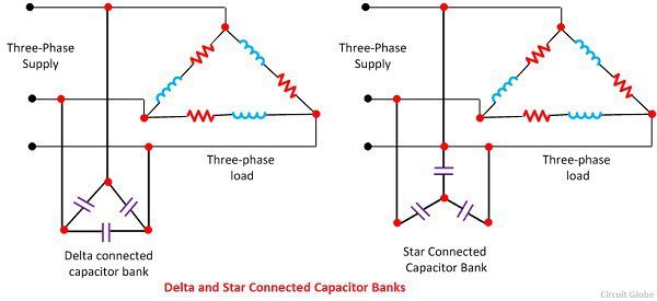
In three phase system, the power factor is improved by connecting the capacitors in star or delta. The star and delta connected banks are shown in the figure below.
 Let, VL = Line voltage
Vp = phase voltage
CΔ = capacitor per phase when the capacitors are connected in delta
Cy = capacitance per phase when the capacitor are connected in stars
Qc = Var rating of each phase
Delta Connection
For these reasons, the capacitors are connected in the delta in three phase system for power factor improvement. Delta connection is also better if the capacitors are designed for higher working voltage.
Power Factor Correction by Using Synchronous Condenser
The power factor can also be correct by installing the specially designed induction motor, known as the synchronous condenser. The synchronous condenser was running without the mechanical load, and it is connected in parallel with the load. It absorbs and generates the reactive power (Var) by varying the excitation of the motor field winding.
The synchronous condenser is used for improving the power factor in bulk. The output of the phase modifier can be varied smoothly. The synchronous condenser has some disadvantage like it is costly and their installation, maintenance and operation are also not easy.


No comments:
Post a Comment