Friday 26 April 2019

Basic of Motor and generator

AC Generators

AC generators are opposite from motors, because they convert mechanical energy into that of electrical. Mechanical energy is used to rotate the loops in the magnetic field, and the generated emf is a sine wave that varies in time. Steam made from burning fossil fuels such as coal, oil and natural gas is a common source in countries like the United States. In Europe, nuclear fission is used to create steam. In some hydroelectric plants, such as those found at Niagara Falls, water pressure is used to rotate the turbines. Turbines are rotors with vanes or blades. Wind and water are not commonly used as fossil fuels for mechanical energy sources because they are not as efficient and are more costly.

AC Motors

Credit: US Department of Energy
AC motors convert electrical energy into that of mechanical. An alternating current is used to rotate the loops in the magnetic field. Most AC motors produce the current by using induction. An electromagnet causes the magnetic field and uses the same voltage as the coils do.

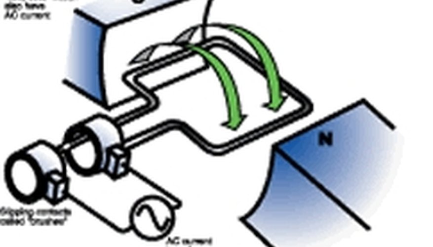
DC Motors and Generators

Credit: US Department of Energy
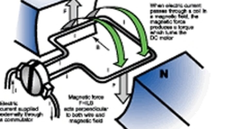
DC motors and generators are similar to their AC counterparts, except that they have a split ring called a commutator. The commutator is attached to electrical contacts called brushes. The changing direction of the current through the commutator causes the armature and thus the loops to rotate. The magnetic field the armature turns in may be a permanent magnet or electromagnet. DC generators have a generated emf is direct current.

Motors Compared to Generators

All motors are generators. The emf in a generator increases its efficiency, but an emf in a motor contributes to energy waste and inefficiency in its performance. A back emf is a resistance to change in a magnetic field. A back emf appears in a motor after it has been turned on, though not immediately. It reduces the current in the loop, and gets larger as the speed of the motor increases.This causes the power requirements of the motor to also increase, especially under loads that are very large.

Monday 22 April 2019

Basic electrical

Basic Elements & Introductory Concepts

Electrical Network:
        A combination of various electric elements (Resistor, Inductor,
Capacitor, Voltage source, Current source) connected in any manner what so ever is
called an electrical network. We may classify circuit elements in two categories, passive
and active elements.

Passive Element:
           The element which receives energy (or absorbs energy) and then
either converts it into heat (R) or stored it in an electric (C) or magnetic (L ) field is
called passive element.

Active Element:
               The elements that supply energy to the circuit is called active element.
Examples of active elements include voltage and current sources, generators, and
electronic devices that require power supplies. A transistor is an active circuit element,
meaning that it can amplify power of a signal. On the other hand, transformer is not an
active element because it does not amplify the power level and power remains same both

in primary and secondary sides. Transformer is an example of passive element.

Bilateral Element:
             Conduction of current in both directions in an element (example:
Resistance; Inductance; Capacitance) with same magnitude is termed as bilateral element.

Unilateral Element:
         Conduction of current in one direction is termed as unilateral
(example: Diode, Transistor) element.

Meaning of Response:
         An application of input signal to the system will produce an
output signal, the behavior of output signal with time is known as the response of the

Linear and Nonlinear Circuits
Linear Circuit: Roughly speaking, a linear circuit is one whose parameters do not
change with voltage or current. More specifically, a linear system is one that satisfies (i)
homogeneity property [response of α u t( ) equals α times the response of u t( ), S ut ( () α )
= α Sut ( ( )) for all α ; and ] (ii) additive property [that is the response of system due
to an input (
u t( )
11 2 2 α ut ut () () +α ) equals the sum of the response of input 1 1 α u t( ) and the
response of input 2 2 α u t( ), 11 2 2 S ut ut ( () ( α +α )) = 11 2 2 α Su t Su t ( ( )) ( ( )) +α .] When an
input is applied to a system “ ”, the corresponding output response of the
system is observed as respectively. Fig. 3.1 explains
the meaning of homogeneity and additive properties of a system.

Saturday 20 April 2019

Passive elements

Passive Elements

Introduction to Electronic Circuits: 1 of 3
The electronic devices we encounter all around us are driven and controlled by the flow of electrical current through electronic circuits. Each circuit is an arrangement of electrical elements designed to perform specific functions. Circuits can be engineered to carry out a wide variety of operations, from simple actions to complex tasks, according to the job(s) the system must perform.
Let's begin by looking at how the key passive elements found in most electronic circuits work.
A passive element is an electrical component that does not generate power, but instead dissipates, stores, and/or releases it. Passive elements include resistances, capacitors, and coils (also called inductors). These components are labeled in circuit diagrams as Rs, Cs and Ls, respectively. In most circuits, they are connected to active elements, typically semiconductor devices such as amplifiers and digital logic chips.

Resistors

A resistor is a primary type of physical component that is used in electronic circuits. It has two (interchangeable) leads. The material placed internally between the two leads of a resistor opposes (restricts) the flow of current. The amount of that opposition is called its resistance, which is measured in ohms (Ω). Resistors are used to control the various currents in areas of a circuit and to manage voltage levels at different points therein by producing voltage drops. When a voltage is applied across a resistor, current flows through it. Ohm's law for resistors is E = IR, where E is the voltage across the resistor, R is the resistance of the resistor, and I is the current flowing through the resistor. That current is proportional to the applied voltage, and inversely proportional to the resistance. Thus, as resistance goes up, the current through the element comes down, so that at high resistances the current is very small.
Ohm's law makes it possible to calculate any one of three circuit values (current, voltage, or resistance) from the other two.

Capacitors

A capacitor is another primary type of physical component used in electronic circuits. It has two leads and is used to store and release electric charge. A capacitor's ability to store charge is referred to as its capacitance, measured in farads (F).
A typical capacitor takes the form of two conductive plates separated by an insulator (dielectric). This type of circuit element cannot pass direct current (DC) because electrons cannot flow through the dielectric. However, a capacitor does pass alternating current (AC) because an alternating voltage causes the capacitor to repeatedly charge and discharge, storing and releasing energy. Indeed, one of the major uses of capacitors is to pass alternating current while blocking direct current, a function called 'AC coupling'.
When a direct current flows into a capacitor, a positive charge rapidly builds up on the positive plate and a corresponding negative charge fills the negative plate (see Figure 1). The buildup continues until the capacitor is fully charged—i.e., when the plates have accumulated as much charge (Q) as they can hold. This amount is determined by the capacitance value (C) and the voltage applied across the component: (Q = CV). At that point, current stops flowing (see Figure 2).
Figure 1 The Capacitor is Charging, Figure 2 The Capacitor is Charged (and Stable)
Figure 1: The capacitor is charging / Figure 2: The capacitor is charged (and stable)

Thursday 18 April 2019

Kirchoff's of laws

Kirchoff got himself a huge name in physics by simply applying two principles of physics to electrical circuits. This is the first:
At any junction in a circuit, the sum of the currents arriving at the junction = the sum of the currents leaving the junction.
In other words - charge is conserved. If this doesn't happen you'd either get a massive build-up of electrons at a junction in a circuit or you would be creating charge from nowhere! That's not going to happen.
Kirchoff's First Law
Current in = Current out
I1 = I2 + I3 + I4
Here is the second principle:
In any loop (path) around a circuit, the sum of the emfs = the sum of the pds.
In other words - energy is conserved. The total amount of energy put in (sum of the emfs) is the same as the total amount of energy taken out (sum of the pds).
Note: pd = V = IR so Copyright S-cool
Kirchoff's First and Second Laws
Energy in = Energy out
emf = pd1 + pd2 + pd3 + pd4
The reason Kirchoff's Laws strike fear into A-level students is because you have to be careful about how you apply them. Once you've got the hang of them, they aren't that hard. Stick to these rules and you'll be OK.
Example Questions using Kirchoff's Laws:
  1. Use Kirchoff's Laws to find the internal resistance of the cell.
    Kirchoff's First and Second Laws
    There are a number of ways to attempt this question, but here is one example using the 2nd Law...
    Energy in = Energy out, and V = IR, so
    10 V = (0.3 x 4) + (0.3 x 3) + (0.3 x r)
    10 = 1.2 + 0.9 + 0.3r
    7.9 = 0.3r, so r = 26.3 Ω
  2. Use Kirchoff's Laws to find the emf of the cell.
    Kirchoff's First and Second Laws
    Again, this can be approached a number of ways, but this time we will start with Law 1...
    Current in = Current out
    This tells us that the current through each 5 Ω resistor is 1.5 A.
    Law 2 tells us that:
    Emf = (3x4) + (1.5x5) + (3x2.5)
    Emf = 12 + 7.5 + 7.5 = 27 V

Tuesday 16 April 2019

Series and parallel tesistances

Resistances in Series

Definition :-    
    Imagine two or more resistors in series, i.e. connected one after another so that the same current flows through them. The total resistance of the collection is the sum of individual resistances. 
    Suppose a current i flows through the resistances. The potential difference V between the points P and Q is the sum of voltage differences across the sequence of resistors, i.e., i( R1 +  R2  +  R3  +.............+ Rn ), and the current flowing is i, so that the resistance is
( V / i )    =   R    =   R1  +  R2   +  R3  +  ..............   +  Rn  .......................(1

Total resistance calculation click here


Resistance in Parallel

        In the given figure, we show 3 resistors connected 'in parallel' with one another. In this  case, the current flowing into P is divided among the 3 resistors:

i = i1 + i2 + i3
However, the potential difference across any resistors  is the same, namely
i1 R1 = i2 R2 = 13 R3
These equations can be thought of as determining the currents i1, i2, i3.
Substituting, We have
i = ( V/R1 + V/R2 + V/R3 ) = V / R 
or
1/R1 + 1/R2 + 1/R3 = 1 / R. 
Similarly, For n number of resistors connected in parallel,
    The Total Equivalent resistance = 1/R1 + 1/ R2 +.......+ 1/Rn = 1 / R. 


Watch:


Sunday 14 April 2019

Difference between voltage and current

 Current:
             It is the rate at which electric charge flows past a point in a circuit
Voltage :
           It is the electrical force that would drive an electric current between two points.


Comparison chart

Current versus Voltage comparison chart
CurrentVoltage
SymbolIV
DefinitionCurrent is the rate at which electric charge flows past a point in a circuit. In other words, current is the rate of flow of electric charge.Voltage, also called electromotive force, is the potential difference in charge between two points in an electrical field. In other words, voltage is the "energy per unit charge”.
UnitA or amps or amperageV or volts or voltage
RelationshipCurrent is the effect (voltage being the cause). Current cannot flow without Voltage.Voltage is the cause and current is its effect. Voltage can exist without current.
Measuring InstrumentAmmeterVoltmeter
SI Unit1 ampere =1 coulomb/second.1 volt = 1 joule/coulomb. (V=W/C)
Field createdA magnetic fieldAn electrostatic field
In series connectionCurrent is the same through all components connected in series.Voltage gets distributed over components connected in series.
In a parallel connectionCurrent gets distributed over components connected in parallel.Voltages are the same across all components connected in parallel.
  

Relationship Between Voltage and Current

Current and voltage are two fundamental quantities in electricity. Voltage is the cause and current is the effect.
The voltage between two points is equal to the electrical potential difference between those points. It is actually the electromotive force (emf), responsible for the movement of electrons (electric current) through a circuit. A flow of electrons forced into motion by voltage is current. Voltage represents the potential for each Coulomb of electric charge to do work.

Series and Parallel connections

In a series circuit

Voltages add up for components connected in series. Currents are the same through all components connected in series.
Electrical components in a series connection
magnify
Electrical components in a series connection
For example if a 2V battery and a 6V battery are connected to a resistor and LED in series, the current through all the components would be same (say, 15mA) but the voltages will be different (5V across the resistor and the 3V across the LED). These voltages add up to the battery voltage: 2V + 6V = 5V + 3V.

In a parallel circuit

Currents add up for components connected in parallel. Voltages are the same through all components connected in parallel.
Electrical components in a parallel connection
magnify
Electrical components in a parallel connection
For example if the same batteriesare connected to a resistor and LEDin parallel, the voltage through the components would be the same (8V). However, the 40mA current through the battery is distributed over the two paths in the circuit and get broken down to 15mA and 25mA.

Basic of eee Ohm's law

Ohm's Law

Ohm's law shows a linear relationship between the voltage and the current in an electrical circuit.


Ohm's law formula

The resistor's current I in amps (A) is equal to the resistor's voltage V in volts (V) divided by the resistance R in ohms (Ω):
V is the voltage drop of the resistor, measured in Volts (V). In some cases Ohm's law uses the letter E to represent voltage. Edenotes electromotive force.
I is the electrical current flowing through the resistor, measured in  Amperes (A)
R is the resistance of the resistor, measured in Ohms (Ω)

Voltage calculation

When we know the current and resistance, we can calculate the voltage.
The voltage V in volts (V) is equal to the to the current I in amps (A) times the resistance R in ohms (Ω):
V=I\times R

Resistance calculation

When we know the voltage and the current, we can calculate the resistance.
The resistance R in ohms (Ω) is equal to the voltage V in volts (V) divided by the current I in amps (A):
R=\frac{V}{I}
Since the current is set by the values of the voltage and resistance, the Ohm's law formula can show that:
  • If we increase the voltage, the current will increase.
  • If we increase the resistance, the current will reduce.

Example #1

Find the current of an electrical circuit that has resistance of 50 Ohms and voltage supply of 5 Volts.
Solution:
V = 5V
R = 50Ω
I = V / R = 5V / 50Ω = 0.1A = 100mA

Example #2

Find the resistance of an electrical circuit that has voltage supply of 10 Volts and current of 5mA.
Solution:
V = 10V
I = 5mA = 0.005A
R = V / I = 10V / 0.005A = 2000Ω = 2kΩ

Ohm's Law for AC Circuit

The load's current I in amps (A) is equal to the load's voltage VZ=V in volts (V) divided by the impedance Z in ohms (Ω):
V is the voltage drop on the load, measured in Volts (V)
I is the electrical current, measured in Amps (A)
Z is the impedance of the load, measured in Ohms (Ω)

Example #3

Find the current of an AC circuit, that has voltage supply of 110V∟70° and load of 0.5kΩ∟20°.
Solution:
V = 110V∟70°
Z = 0.5kΩ∟20° = 500Ω∟20°
I = V / = 110V∟70° / 500Ω∟20° = (110V / 500Ω) ∟ (70°-20°) = 0.22A ∟50°

Advantages of 3 Phase Over Single Phase System

Advantages of 3 Phase Over Single Phase System The three-phase system has three live conductors which supply the 440V to the large consu...